cocotbext-ams
![]()
cocotbext-ams
An analog simulator bridge for cocotb — open-source mixed-signal co-simulation

![]()

Table of Contents
- Overview
- Prerequisites
- Installation
- Quick Start
- API Reference
- Tutorial: PWM DAC with SAR Controller
- Examples
- Architecture Details
- Troubleshooting
Overview
cocotbext-ams synchronizes cocotb’s digital simulation with an analog SPICE simulator via shared library APIs. It supports ngspice (default) and Xyce (Sandia’s open-source parallel SPICE), allowing you to co-simulate SPICE netlists alongside Verilog/VHDL testbenches using entirely open-source tools.
How it works
cocotb testbench (Python async)
       |
       v
MixedSignalBridge (orchestrator)
  |-- reads Verilog signals via cocotb handles
  |-- converts digital <-> analog (threshold-based)
  '-- drives simulator via SimulatorInterface
       |                         |
       v                         v
  HDL Simulator           libngspice.so  or  libxycecinterface.so
  (Icarus/Verilator)      (ngspice 45+)     (Xyce 7+)
The bridge uses event-driven synchronization: instead of exchanging signals at a fixed interval, it reacts to actual signal changes:
- Digital → Analog:
ValueChangemonitor coroutines update voltage source values the instant a Verilog signal changes — no sync overhead needed. - Analog → Digital: Threshold-crossing detection triggers an immediate sync when a SPICE output crosses a digital threshold, forcing the new value onto the Verilog signal.
- A configurable maximum sync interval (default 100 ns) ensures periodic fallback synchronization even when no crossings occur.
Supported simulators:
- ngspice (default) — callback-driven via libngspice’s shared library API
- Xyce — explicit stepping via Xyce’s C interface (
xyce_simulateUntil())
Signal bridging:
- Digital → Analog: Verilog 1/0 mapped to VDD/VSS via voltage sources in SPICE
- Analog → Digital: SPICE node voltage compared against a threshold (with optional hysteresis), result forced onto Verilog output
- Analog-only pins: remain X in Verilog, fully simulated in SPICE
Waveform output:
Pass analog_vcd="file.vcd" to record SPICE node voltages as real-typed VCD
signals alongside digitized outputs as wire signals. Load this VCD with the
HDL simulator’s digital VCD to see everything together:
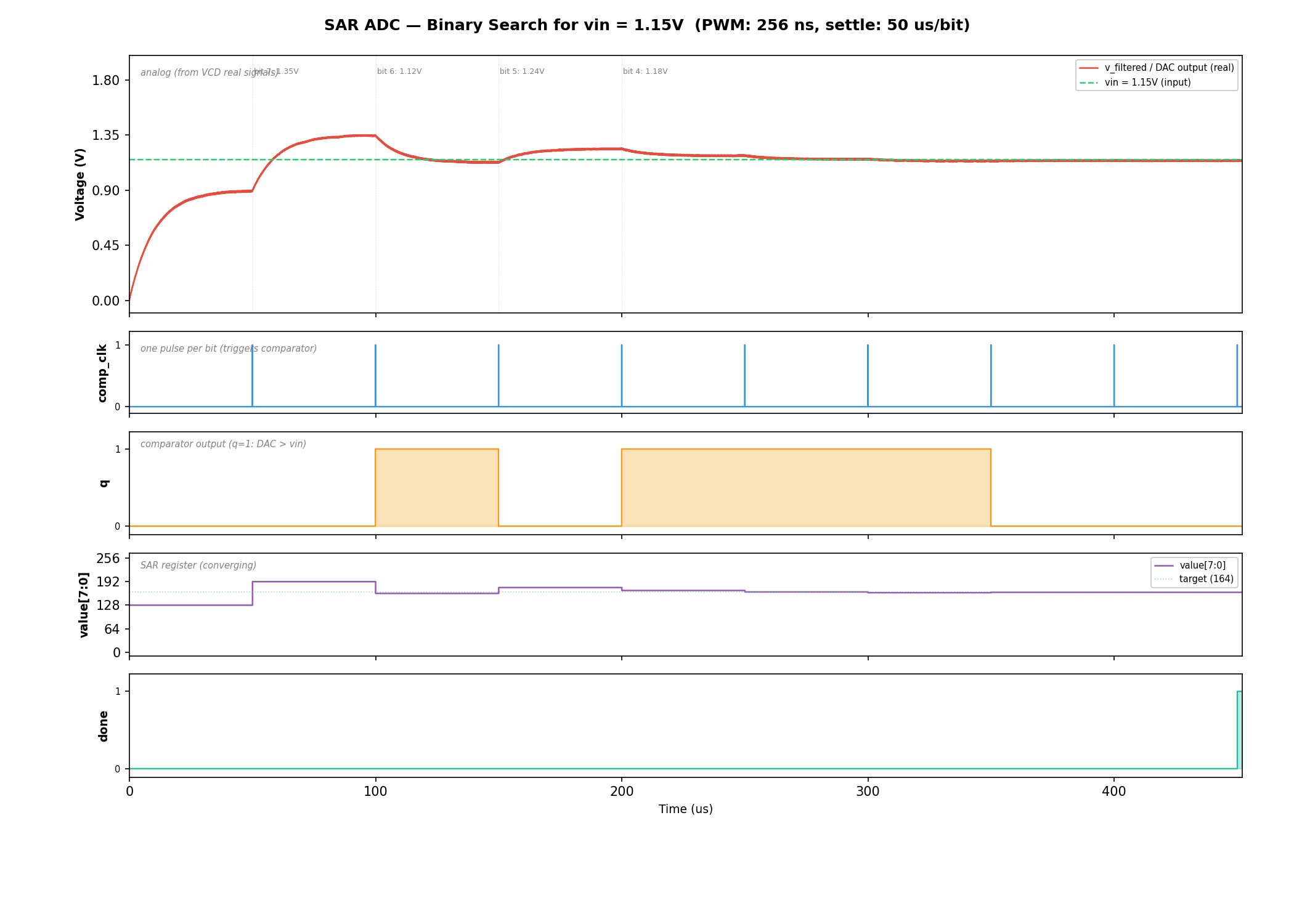
SAR ADC binary search: RC-filtered DAC output converging to vin (top), comparator output q (second), SAR value register (third), and done signal (bottom). See the full tutorial for details.
Prerequisites
- Python >= 3.10
- cocotb >= 2.0
- ngspice shared library (
libngspice.so/libngspice.dylib) or Xyce shared library (libxycecinterface.so) - A Verilog simulator supported by cocotb (e.g., Icarus Verilog)
Installing ngspice
Ubuntu/Debian:
sudo apt-get install libngspice0-dev
Fedora/RHEL:
sudo dnf install libngspice-devel
macOS (Homebrew):
brew install ngspice
Conda (any platform):
conda install -c conda-forge ngspice
Building ngspice from source
If your distribution doesn’t package the shared library, or you need a specific version:
cd ngspice
mkdir build && cd build
../configure --with-ngshared --enable-xspice --enable-cider
make -j$(nproc) && sudo make install
Installing Xyce
Xyce is an open-source parallel SPICE simulator from Sandia National Laboratories.
To use Xyce with cocotbext-ams, you need the shared library build
(libxycecinterface.so).
See the Xyce installation guide for build instructions. When building, enable the shared library:
cmake -DBUILD_SHARED_LIBS=ON ...
If the library is installed in a non-standard location, pass the path explicitly:
bridge = MixedSignalBridge(dut, blocks, simulator_lib="/path/to/libxycecinterface.so")
Installation
pip install cocotbext-ams
Or install from GitHub for the latest development version:
pip install git+https://github.com/VLSIDA/cocotbext-ams.git
For local development:
git clone https://github.com/VLSIDA/cocotbext-ams.git
pip install -e cocotbext-ams
Quick Start
1. Write your SPICE subcircuit
* my_block.sp
.subckt my_block clk data_in data_out vdd vss
* ... your analog circuit ...
.ends my_block
2. Write a Verilog black-box stub
module my_block(
    input  wire       clk,
    input  wire       data_in,
    output reg        data_out,   // reg so bridge can Force
    input  wire       ain         // analog-only, stays X
);
    initial data_out = 1'bx;
endmodule
3. Write your cocotb test
import cocotb
from cocotb.clock import Clock
from cocotb.triggers import RisingEdge, Timer
from cocotbext.ams import AnalogBlock, DigitalPin, MixedSignalBridge

@cocotb.test()
async def test_my_block(dut):
    block = AnalogBlock(
        name="dut",
        spice_file="my_block.sp",
        subcircuit="my_block",
        digital_pins={
            "clk":      DigitalPin("input"),
            "data_in":  DigitalPin("input"),
            "data_out": DigitalPin("output"),
        },
        analog_inputs={"ain": 0.9},
        vdd=1.8,
    )

    bridge = MixedSignalBridge(dut, [block], max_sync_interval_ns=10)
    await bridge.start(duration_ns=50_000, analog_vcd="analog.vcd")

    cocotb.start_soon(Clock(dut.clk, 100, "ns").start())
    await Timer(1, "us")

    # Read result
    result = int(dut.data_out.value)

    # Change analog input at runtime
    bridge.set_analog_input("dut", "ain", 1.2)

    await bridge.stop()
The analog_vcd parameter writes a VCD file with real-typed signals at
full simulator resolution. Load it alongside the HDL simulator’s digital VCD
in Surfer, GTKWave, or any viewer that supports real-valued VCD signals to
see analog and digital waveforms together.
Using Xyce instead of ngspice
block = AnalogBlock(
    name="dut",
    spice_file="my_block.sp",
    subcircuit="my_block",
    digital_pins={...},
    analog_inputs={"ain": 0.9},
    vdd=1.8,
    simulator="xyce",              # use Xyce instead of ngspice
)

bridge = MixedSignalBridge(dut, [block],
                           simulator_lib="/path/to/libxycecinterface.so")
await bridge.start(duration_ns=50_000)
The bridge auto-generates a Xyce-compatible netlist (YDAC devices, .TRAN,
.PRINT TRAN) and drives the simulation via Xyce’s explicit stepping API.
API Reference
DigitalPin(direction, width=1, vdd=1.8, vss=0.0, threshold=None, hysteresis=0.0)
Configures how a pin is bridged between digital and analog domains.
| Parameter | Description |
|---|---|
direction |
"input" (digital drives analog) or "output" (analog drives digital) |
width |
Bit width. Multi-bit pins get one SPICE source/probe per bit. |
vdd |
Logic-high voltage level |
vss |
Logic-low voltage level |
threshold |
Voltage threshold for A/D conversion. Default: (vdd + vss) / 2 |
hysteresis |
Total hysteresis band. When > 0, rising transitions require >= threshold + hysteresis/2 and falling transitions require < threshold - hysteresis/2. Prevents rapid oscillation around the threshold. Default: 0.0 |
AnalogBlock(name, spice_file, subcircuit, ...)
Describes an analog block (SPICE subcircuit) to be co-simulated.
| Parameter | Description |
|---|---|
name |
Instance name matching the Verilog stub hierarchy |
spice_file |
Path to the SPICE netlist |
subcircuit |
Name of the .subckt |
digital_pins |
dict[str, DigitalPin] — pin name to configuration |
analog_inputs |
dict[str, float] — analog input name to initial voltage (changeable at runtime) |
vdd |
Supply voltage (default 1.8) |
vss |
Ground voltage (default 0.0) |
tran_step |
SPICE transient step size (default "0.1n") |
extra_lines |
Additional SPICE lines for the generated netlist (e.g., .include directives for PDK libraries) |
simulator |
"ngspice" (default) or "xyce" |
MixedSignalBridge(dut, analog_blocks, max_sync_interval_ns=100.0, simulator_lib=None)
The main orchestrator.
| Parameter | Description |
|---|---|
dut |
cocotb DUT handle |
analog_blocks |
List of AnalogBlock descriptions |
max_sync_interval_ns |
Maximum time between sync points in nanoseconds (default 100.0) |
simulator_lib |
Path to the simulator shared library (auto-detected if None) |
| Method | Description |
|---|---|
await start(duration_ns, analog_vcd=None, vcd_nodes=None) |
Load circuit, start co-simulation. Pass analog_vcd="file.vcd" to record analog waveforms. vcd_nodes adds extra SPICE nodes beyond the auto-included output pins. |
await stop() |
Halt simulation, release forced signals |
set_analog_input(block, name, voltage) |
Change an analog input voltage at runtime |
get_analog_voltage(block, node) |
Probe any SPICE node voltage |
Migration note: The old
ngspice_libparameter still works but emits aDeprecationWarning. Rename it tosimulator_lib.
Sync interval selection
Synchronization is primarily event-driven — threshold crossings on analog
outputs trigger immediate sync. The max_sync_interval_ns parameter sets a
ceiling that bounds time drift and ensures digital-side events are processed:
- 10-50 ns: Tight ceiling, suitable when digital-side timing is critical
- 100 ns (default): Good balance for most designs
- 1000+ ns: Loose ceiling, relies mostly on event-driven sync
Tutorial
PWM DAC with SAR Controller — A complete walkthrough of a mixed-signal co-simulation: a hardware SAR controller binary-searches PWM duty cycles through an RC filter and sky130 latch comparator to find the voltage matching a reference. Covers both data paths, runtime analog control, VCD export, and waveform viewing.
Examples
examples/sar_adc/— 10-bit SAR ADC with behavioral SPICE modelexamples/pll/— Charge-pump PLL with digital PFD
Architecture Details
Simulator abstraction
Both ngspice and Xyce inherit from SimulatorInterface, which holds all
shared state (voltage source values, node voltages, crossing detection,
VCD writer) and implements common logic (_check_crossings(),
_write_vcd()). Subclasses implement the simulator-specific ctypes wrapper
and control flow.
Thread model
The bridge uses cocotb’s @bridge / @resume mechanism for thread
synchronization. Both simulators run a blocking simulation in a
@bridge thread and periodically call a @resume function at sync points:
ngspice:
@bridgeruns ngspice’s blockingtrancommand in a dedicated thread.GetVSRCDatafires on every ngspice evaluation step, reading the_vsrc_valuesdict (updated asynchronously byValueChangemonitors).SendDatafires after each accepted timestep — the bridge checks all output pin voltages against their thresholds (with hysteresis).GetSyncDatafires at each internal timestep. If a crossing was detected (or the fallback interval elapsed), it calls a@resumefunction that blocks the ngspice thread and transfers control to the cocotb scheduler.
Xyce:
@bridgeruns an explicit stepping loop in a dedicated thread.- At each step: push VSRC values via
xyce_updateTimeVoltagePairs(), advance viaxyce_simulateUntil(), read voltages viaxyce_obtainResponse(), check crossings. - At sync intervals, calls the same
@resumefunction as ngspice.
Common to both:
- The cocotb scheduler forces new digital values onto Verilog and advances
digital time by the actual elapsed SPICE time via
await Timer(...). - When the
@resumefunction returns, the simulator thread resumes.
This is event-driven: sync only happens when analog outputs actually cross a digital threshold, or at the fallback ceiling interval.
Netlist augmentation
The bridge auto-generates a wrapper SPICE deck around the user’s subcircuit, with simulator-specific syntax:
| Feature | ngspice | Xyce |
|---|---|---|
| Runtime sources | v_name node 0 dc 0 external |
YDAC v_name DAC node 0 |
| Output probing | .save v(node) |
.PRINT TRAN v(node) |
| Transient analysis | .tran step stop uic |
.TRAN step stop |
| End marker | .end |
.END |
Power supplies are standard DC sources in both formats.
Vector name normalization
ngspice may report vector names with plot prefixes (e.g., tran1.v(d0)) or
wrapped in v(). The bridge normalizes lookups so you can query by bare node
name (d0), v(d0), or the full qualified name. Xyce stores both the
expression form and bare name.
Troubleshooting
Simulator library not found
FileNotFoundError: Cannot find libngspice shared library.
Install the ngspice or Xyce shared library for your platform (see Prerequisites above). If the library is installed in a non-standard location, pass the path explicitly:
# ngspice
bridge = MixedSignalBridge(dut, blocks, simulator_lib="/path/to/libngspice.so")

# Xyce
bridge = MixedSignalBridge(dut, blocks, simulator_lib="/path/to/libxycecinterface.so")
Signal not found
AttributeError: Cannot find signal 'q' on block 'dut.u_analog'
The block name must match your Verilog hierarchy. If the SPICE stub module
pwm_dac is instantiated as u_analog inside a dut wrapper, use
name="dut.u_analog". The pin name must match a port on the stub module.
Sawtooth on filtered output
If the RC filter output looks like a sawtooth instead of a smooth DC level, the PWM period is too close to the RC time constant. The PWM period should be at least 10-40x smaller than τ:
- τ = 10kΩ × 1nF = 10μs → PWM period should be ≤ 1μs (≥ 1MHz clock)
- τ = 10kΩ × 100pF = 1μs → PWM period should be ≤ 100ns (≥ 10MHz clock)
Simulation hangs
If the simulation appears to hang, check:
- Missing
ValueChangesupport: Some simulators don’t supportValueChange. The bridge logs a warning and falls back to sync-point updates. Check your cocotb log output. - Too-tight sync interval: Very small
max_sync_interval_nsvalues (< 1ns) can make the simulation extremely slow. Start with 50-100ns. - Simulator convergence: Complex SPICE circuits may fail to converge.
Check the cocotb log for
ngspice: stderrwarnings (ngspice) or Xyce error messages.
Debugging sync behavior
Enable debug logging to see threshold crossings and sync points:
import logging
logging.getLogger("cocotbext.ams").setLevel(logging.DEBUG)
This shows each threshold crossing event with timestamp, pin name, old/new values, and voltages.