Static Timing Analysis (STA) Tutorial
Static Timing Analysis is the exhaustive, non-simulation check that every path in a synchronous design meets its timing requirements (setup, hold, recovery, removal) against a clock. It’s called “static” because the tool walks the netlist once and computes worst-case arrival times from pin-to-pin delays — no vectors required — so coverage is 100 % of paths by construction.
Tools
The open-source STA engine used in this tutorial chain is OpenSTA. It’s available two ways:
- Standalone CLI:
sta. - Embedded in OpenROAD, which is how most of the ORFS and LibreLane flows invoke it.
Inside OpenROAD or ORFS, drop into the interactive shell:
$ openroad
OpenROAD edf00dff99f6c40d67a30c0e22a8191c5d2ed9d6
Features included (+) or not (-): +Charts +GPU +GUI +Python
This program is licensed under the BSD-3 license. See the LICENSE file for details.
Components of this program may be licensed under more restrictive licenses which must be honored.
openroad>
Every STA command in these tutorials is a TCL command entered at this prompt. TCL (Tool Command Language) is the industry-standard scripting language for EDA — not because it’s a great language, but because nearly every commercial tool (Design Compiler, PrimeTime, ICC, Innovus, Tempus) reads it, and your flow will need to work with those tools eventually. OpenROAD also exposes a Python interface (see OpenROAD Python API) but the TCL commands below are the common form.
Full OpenSTA command reference: https://github.com/The-OpenROAD-Project/OpenSTA/blob/master/doc/OpenSTA.pdf.
Example design
This tutorial uses the SPM (serial-parallel multiplier) design bundled in this repository as final.tar.gz. The tarball was produced by a LibreLane run so it contains every view you might want to load: DEF, ODB, gate-level Verilog, SDC, and per-corner SPEFs.
git clone https://github.com/VLSIDA/chip-tutorials.git
cd chip-tutorials
tar -zxvf final.tar.gz
This creates a final/ directory with the subdirectories def, odb, pnl (gate-level Verilog), sdc, spef, and lib.
Set PDK_ROOT to your ciel PDK install (see Sky130 PDK):
export PDK_ROOT=~/.ciel
This is the same variable LibreLane and ORFS use — if one of those is already set up, you can skip this.
Single corner timing analysis
There are four main steps to setting up a timing analysis.
- Read in the library file(s)
- Read in the design file(s)
- Read in the parasitic file(s)
- Read in the constraints
The following is an example that does each of these steps:
read_lib $env(PDK_ROOT)/sky130A/libs.ref/sky130_fd_sc_hd/lib/sky130_fd_sc_hd__ss_100C_1v60.lib
read_db odb/spm.odb
read_spef spef/max/spm.max.spef
read_sdc sdc/spm.sdc
Other ways to read the design file(s)
Instead of reading the ODB (OpenROAD database format) file, you can use gate-level verilog file or the DEF (Design Exchange Format) file. You may need to do this depending on what output is available from the steps of the design flow (i.e. they don’t all save ODB files). However, these both require that you also read in the LEF technology and cell files. This would replace the reading of the design above with these multiple steps like this for the DEF:
read_lef $env(PDK_ROOT)/sky130A/libs.ref/sky130_fd_sc_hd/techlef/sky130_fd_sc_hd__nom.tlef
read_lef $env(PDK_ROOT)/sky130A/libs.ref/sky130_fd_sc_hd/lef/sky130_fd_sc_hd.lef
read_lef $env(PDK_ROOT)/sky130A/libs.ref/sky130_fd_sc_hd/lef/sky130_ef_sc_hd.lef
read_def def/spm.def
or like this for the gate-level Verilog:
read_lef $env(PDK_ROOT)/sky130A/libs.ref/sky130_fd_sc_hd/techlef/sky130_fd_sc_hd__nom.tlef
read_lef $env(PDK_ROOT)/sky130A/libs.ref/sky130_fd_sc_hd/lef/sky130_fd_sc_hd.lef
read_lef $env(PDK_ROOT)/sky130A/libs.ref/sky130_fd_sc_hd/lef/sky130_ef_sc_hd.lef
read_verilog nl/spm.nl.v
link_design spm
The other steps (library files, parasitics, and constraints) are the same. Note that with the Verilog method, the link_design command will report a few missing liberty files:
[WARNING ORD-2011] LEF master sky130_ef_sc_hd__decap_12 has no liberty cell.
[WARNING ORD-2011] LEF master sky130_fd_sc_hd__fill_1 has no liberty cell.
[WARNING ORD-2011] LEF master sky130_fd_sc_hd__fill_2 has no liberty cell.
[WARNING ORD-2011] LEF master sky130_fd_sc_hd__tapvpwrvgnd_1 has no liberty cell.
but that is ok since they are special cells that do not have timing.
Reports
The STA Reporting Tutorial goes into more detail on the different reports that can be generated.
Timing Constraints
The STA Timing Constraints Tutorial goes into more detail on the different constraints that can be used.
Multi-Corner STA
The STA Multi-Corner Tutorial goes into more detail on how to set up a multi-corner analysis.
OpenROAD Timing GUI
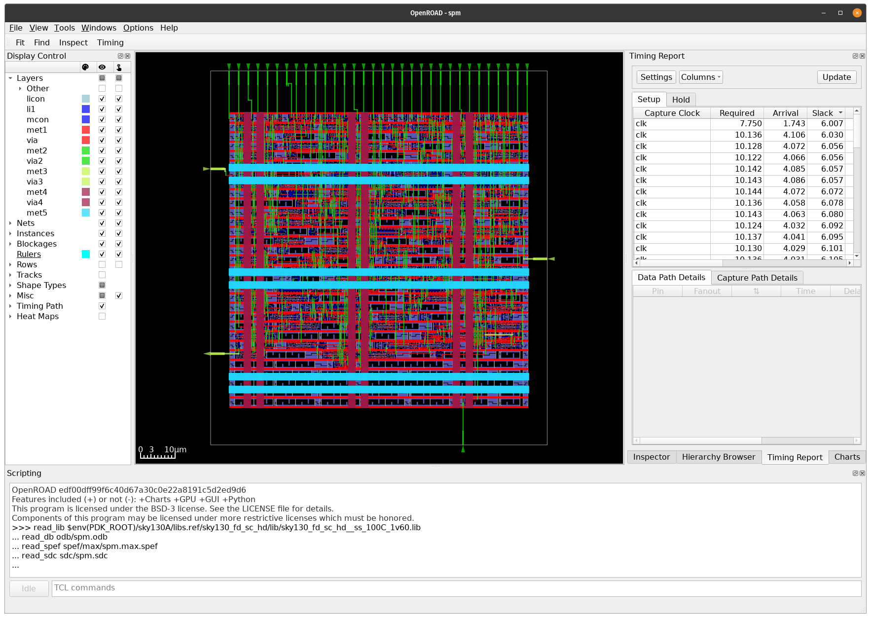
OpenROAD has a GUI that can be used to view the timing results. You can open it by running openroad -gui and running the previous commands in the “TCL Commands” portion of OpenROAD. It is recommended to use the ODB or DEF design files as these have the placement information. Once you do this, click on the “Timing Report” tab and then click the “Update” button to run the timing analysis. You should see something like this:
You can select the top ranked path (and expand the window sizes) to see the details of the path like this:
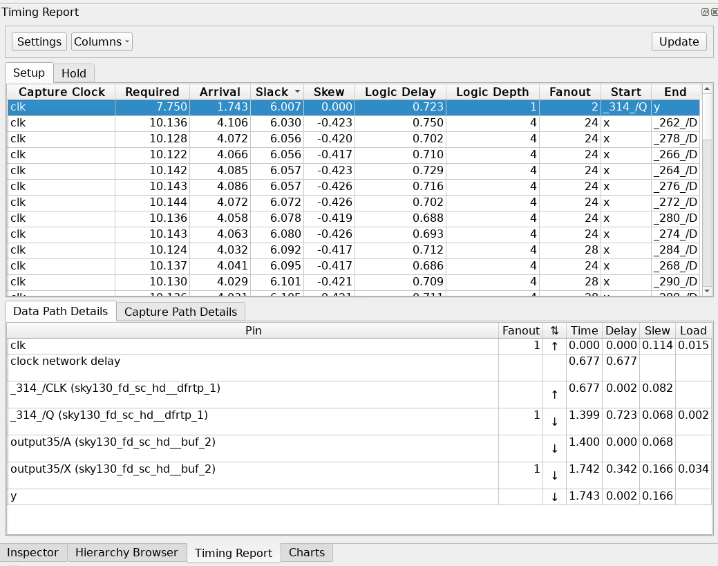
The path should also be highlighted in the layout to see the placement. However, the color defaults to black.